
Universal Ball Lock Lathe Chuck 2B 10” UBLC
GMT LATHE CHUCK CASE STUDY
Universal Ball Lock Lathe Chuck 2B 10” UBLC
RESULT: Time Saved! With the customer’s manual fixture setup,production rate 250 components /12 hours with GMT Chuck was 80 components /12 hours, with the customer’s manual fixture
CUSTOMER : M/s. Shine Auto Pvt Ltd. Mohali, Punjab
[Manufacturers of Auto Components]
COMPONENT : Cylinder Head (RB33 & AVL) for tractor
OPERATION : Facing, counter bore turning & chamfering on a Doosan CNC Lathe
COMPONENT MATERIAL, DIMENSION: Grey Cast iron, L X B X H – 186 x 138 x 107 mm
REQUIRED ACCURACY: Parallelism 50 micrometres
CUSTOMER’S REQUIREMENT::
They wanted a special lathe chuck for mass production instead of clamping the component with a manual fixture.
OUR SOLUTION:
2B 10″ UBLC lathe chuck with top tooling shown in the sketch below consisting of Special Jaws with False Plates and Rest cum Locator. The False Plate is used to preserve the integrity of the lathe chuck, as the component has to be fastened on the face of the chuck with screws. It is instead fastened on the false plate. Another advantage is that the component can be set up on a face plate ready for mounting, thus reducing machine downtime.
The initial solution was given based on the 3d model provided by the customer. During trials with the components, we observed that clamping was improper as one insert was in contact with the component surface and the other insert was in partial contact with the component surface due to the draft angle in the component. So, there was a large variation between the 3D model given to us and the actual component. To solve this issue, the pitch distance between the clamping inserts in the jaws was reduced to 15 mm from 96 mm to ensure a positive face rest against the jaws while clamping the component. The pitch distance between the clamping inserts was 96 mm.
This highlights the importance of initially sending us correct and complete data to reduce the turnaround time from receipt of enquiry to final proposal and then trials. Always sending the correct component info and inspected and approved blanks for trials is critical!
We also suggested that the customer provides max. 0.02 mm clearance on the component blank with Rest cum Locator for easy loading and unloading of the component.
The components’ flatness ranged from 0.013 mm to 0.16 mm. The customer must maintain the flatness of the resting surface of the component blank within 0.03 mm to get the desired results.
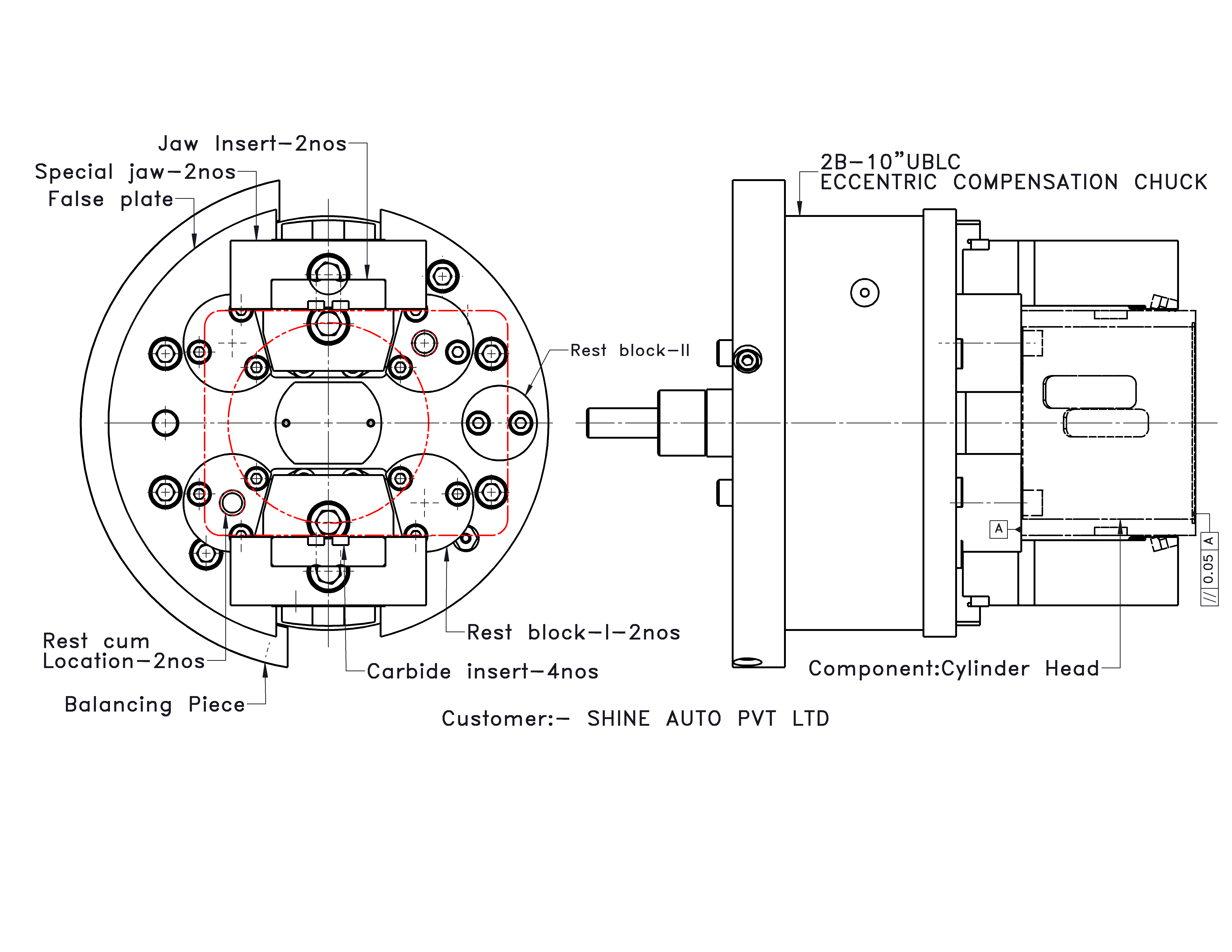
Fig.1 Sketch Showing the Customer’s Components in the Lathe Chuck
and the Accuracy Requirements

Fig. 2 Component: Cylinder Head (RB33 & AVL) Material: Grey Cast-Iron

Fig. 3 Chuck without Component

Fig. 4 Chuck with Component
#GMT #LATHECHUCK #CNCMACHINE #CUSTOMER SATISFACTION #METALWORKING
For more on Universal Ball Lock Lathe Chucks from GMT, check out this page https://gmt.co.in/universal-ball-lock-chuck/